
 Tiếng Việt
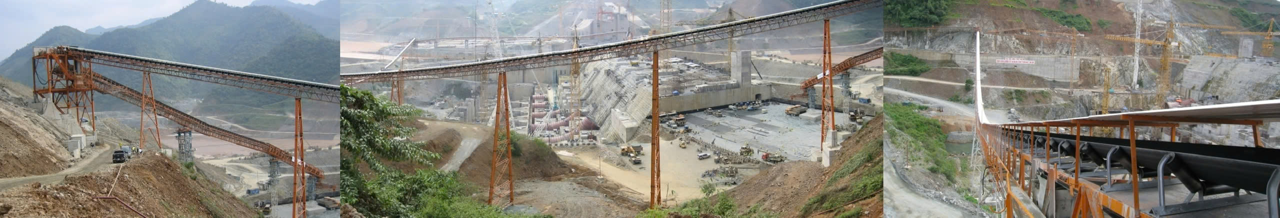

1. Instruction about NC’s Belt Conveyor Pulleys
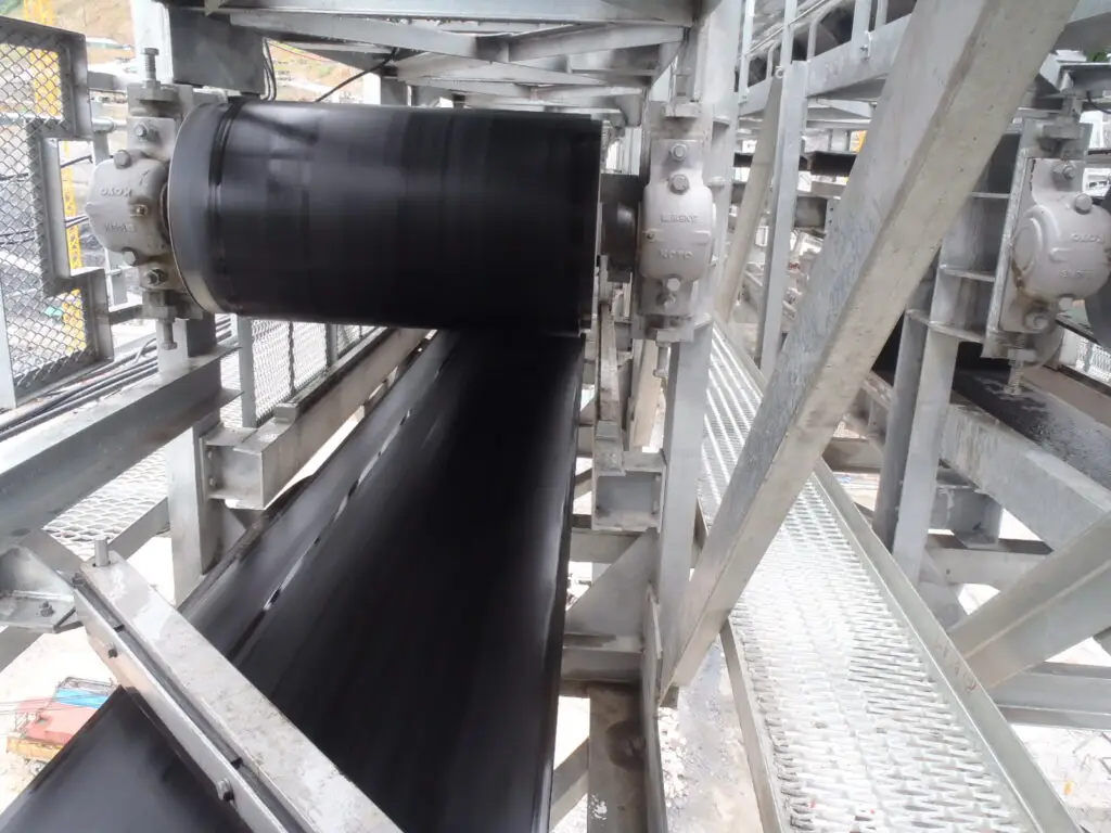
Pulleys may not always appear as significant components in a belt conveyor system, but they play a crucial role in ensuring the system’s successful operation.
Even minimal damage to a pulley can result in the conveyor system becoming inoperative and non-functionality of the conveyor. Especially if when there is critical damage, it can have adverse effects on the overall plant performance.
Despite their seemingly simple structure, pulleys are subject to substantial internal stress as they rotate. Any defect or lack of strength in one of the pulley components can easily lead to breakage.
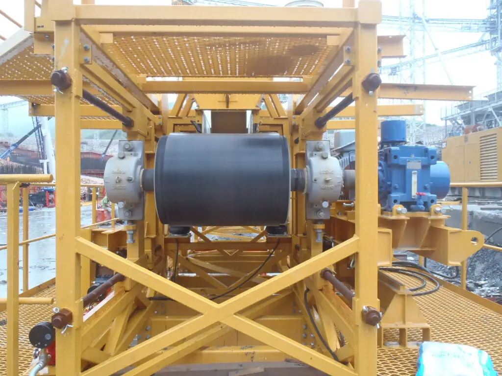
At Nippon Conveyor Co., Ltd., a specialist of belt conveyor systems, we have been dedicating to designing and supplying a variety of belt conveyor systems globally. Our range includes heavy-duty and long-distance conveyors which are used in heavy industries including conveyors in steel mills, earth-moving and reclamation plants, power plants, chemical and cement production plants…
With our extensive experience and on-going research for development, Nippon Conveyor consistently delivers pulleys that meet the evolving requirements for any conveyor systems. Our commitment to up-to-date designs, manufacturing technology, and quality control is certified by ISO 9001 is guaranteed.
2. Structure and Types of Pulley
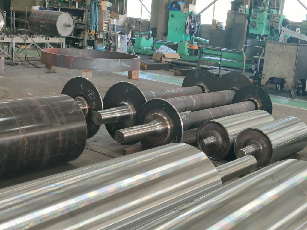
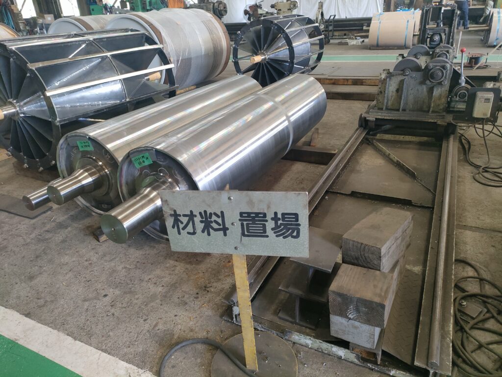
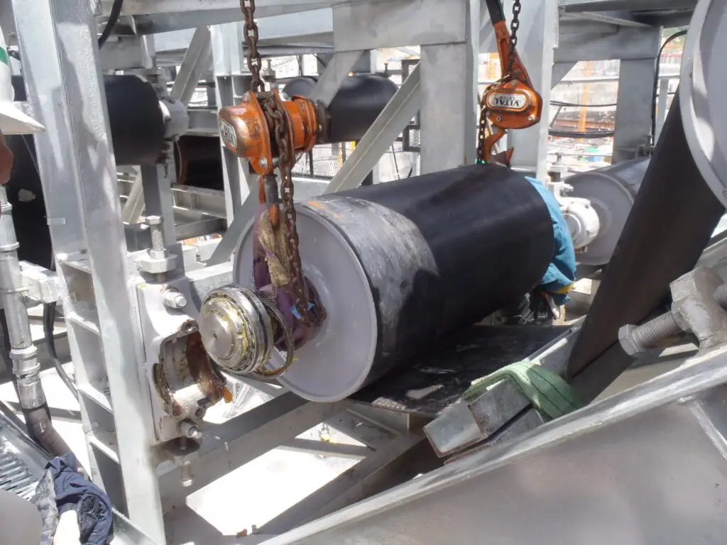
Pulley Structure
A pulley consists of a shell, end discs, hubs, and shaft. A wide variety are available by changing the machining work employed, the welding process for assembly, and shaft-fitting to meet any requirements against load.
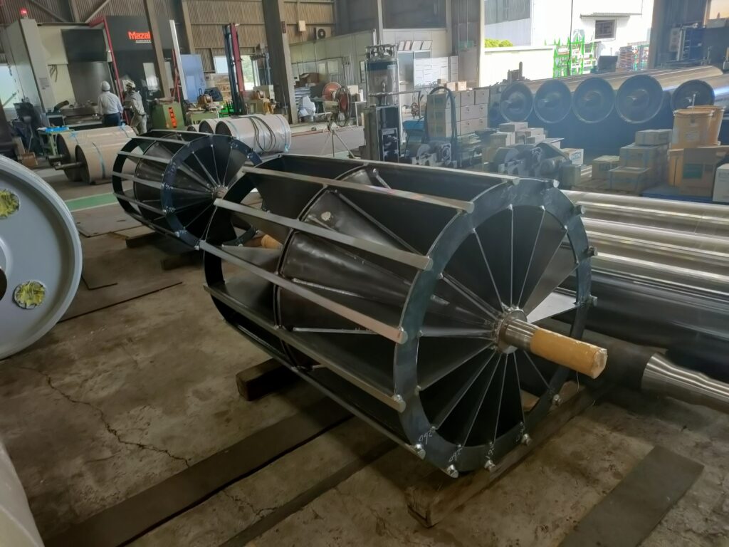
Pulley types
Type of Pulley varies with load (belt tension) and belt width, as shown in the Table below.


3. Designing concept of Pulley
Belt conveyor pulleys are, in general, designed based upon the strength criteria of shaft because the belt tension is supported by the shaft through shell and end-disc.
However, pulley structures, i.e. shell and end-disc, have a different internal stress from shaft strength criteria, corresponding with belt wrap angle and constructural rigidity.
Nippon Conveyor Pulleys are designed for customer’s full reliability with the shell and the end-disc, as well as the shaft altogether are provided with full strength on strict calculation.
4. Pulley structure analysis
A pulley assembled by means of welding consists of a shell, end-discs and a shaft, and the analysis of the stress given on each component shows that stress on each differs respectively with belt tension, the wrap angle and the rigidity of component material.
When belt tension applies to pulley consisting of shell, end-discs and shaft, each part of the pulley is displaced. The structural analysis of this displacement constitutes the calculation of the strength of each part of the pulley

Fig A.
The stress in the direction of right angle against the shaft on end disc is shown in Figure A, where the thick line indicates the outside of end disc, the single dotted chain line for the inside, the thin me
for the stress in the circumferential direction thereby, the double dotted chain line for the outside and the dotted line for the inside.
Fig B.
The thin line shows the shearing stress generated on the shell, the double dotted chain line does the loading side, and the dotted line does the unloaded side.
Shown in this Figure is the stress in the shell longitudina direction. The thick line indicates the contact surface of belt while the single dotted chain line does the backside.

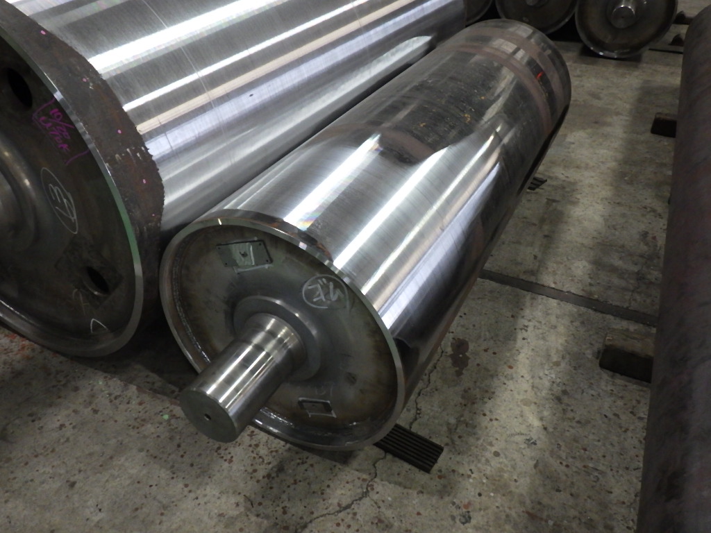
5. Accuracy of Pulley
Pulley Classification
The grade of the pulleys can be classified into 2 grades of A and B according to the difference of outside diameters and the runout on outside diameter.

Tolerances on pulley diameter
The tolerances on the pulley diameter is as own in beside table in accordance with the pulley diameter.
Remark: The tolerance for lagged pulley is available by adding 1mm each to the value of beside table.

Runout on outside diameter
The acceptable value of runouts on outside diameters for pulleys of grade A is as shown in beside table, in accordance with pulley diameter.
Remark:
- The tolerance for the lagged pulley applies to lagging out-side diameter and is obtainable by adding 0.5mm each to the value of beside table
- Above table does not apply to the tolerance of the connected parts due to
cylindical work of outside cylinder and the outside parts of end disc.

Pulley Balance
Grade A drive pulley for belt speed exceeding 3.33m/sec and a belt width of more than 1200mm is also adjusted as to have its balance in accordance with JIS B 905, G40
Pulley Inspection
The inspection shall be carried out according to the grades of the pulleys respectively on the items of below table

6. Specification of pulleys
Structural specifications of belt conveyor pulleys
 Remarks:
⚫ – The standard to be used unless otherwise specified by customer
◯ – The possible choice
N – Stand for the shaft fixation of non-drive pulley
D – Stand for the shaft fixation of drive pulley
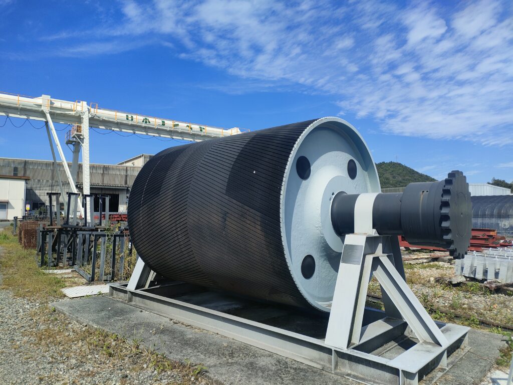
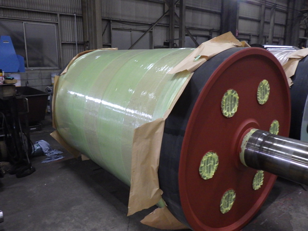
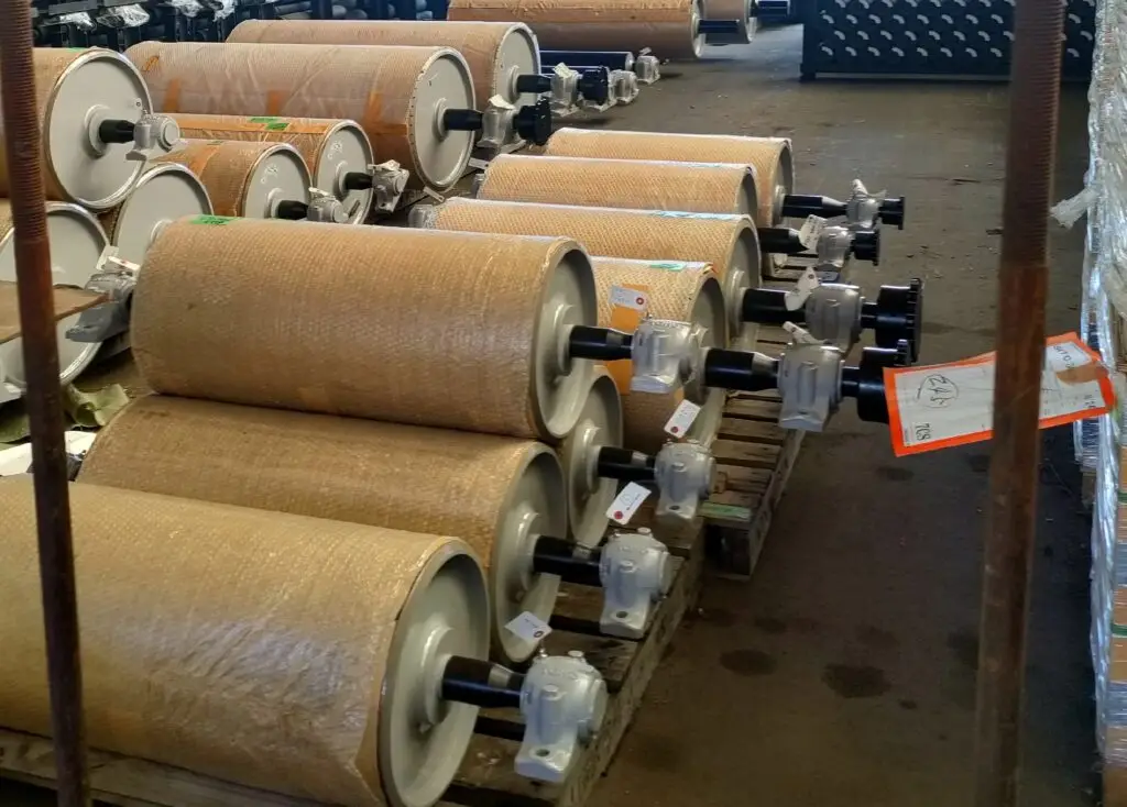
7. Lagging of pulley
Lagging of drive pulley

And various types of lagging customized to specific requirements.
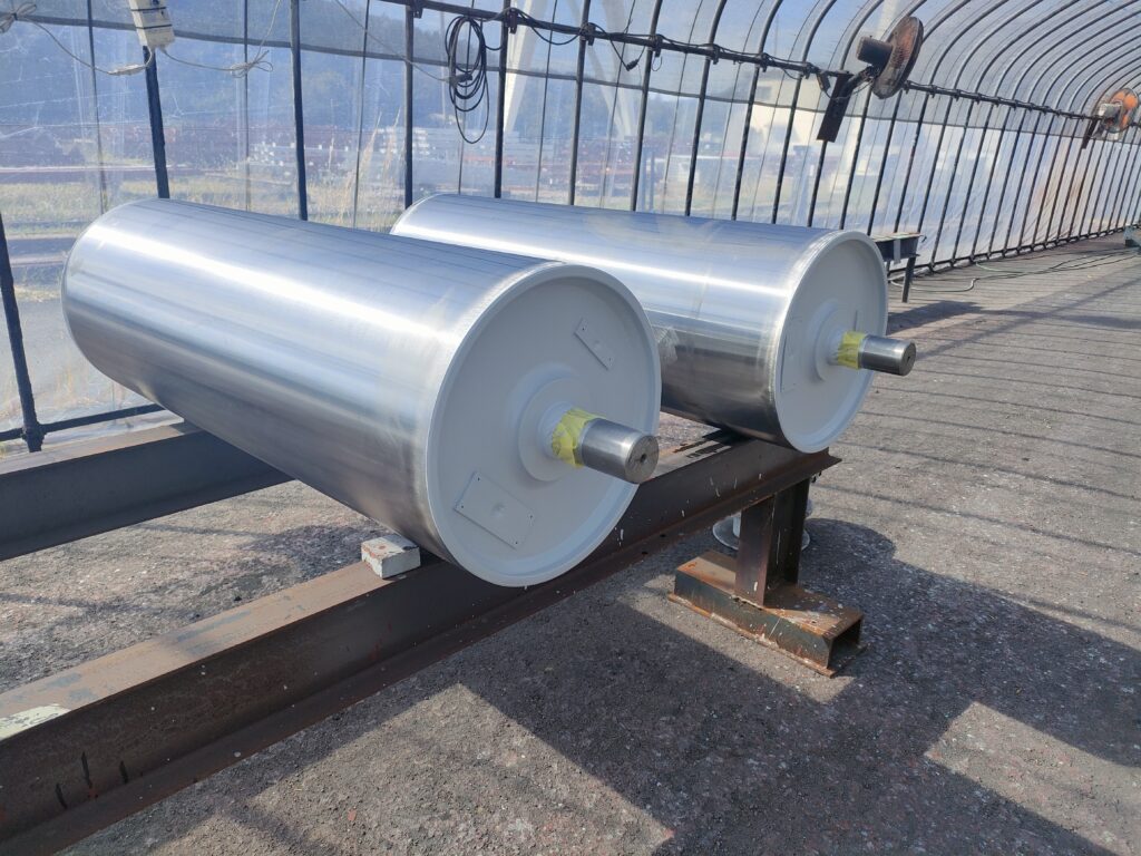
Lagging of non-drive pulley
